A PIC32MZ program skeleton post
How to start every program (at 200Mhz)
Last time I discussed how to set the PIC32 and its peripherals at maximum clock speeds. This time I'll be going over some common "traps for young players", as Dave on EEVBlog would say. The PIC32 is great but starting out can be a nightmare.
TL;DR warning: To be honest, I just want to start writing about how to code this thing but the PIC32MZ has so many traps and pitfalls that I think need to be discussed first. Just download the code at the end :)
Let's take a simple example: I want to turn on an LED on RA0 (aka PORT A bit 0). So, coming from other microcontrollers, I know I need to set the pin to an output. So I make this incredibly simple program:
void main()
{
    set_performance_mode(); // Set everything to maximum speed

    TRISACLR = 1 << 0; // Clear bit 0 of TRISA. which makes PORT A bit 0 an output

    LATASET = 1 << 0; // Set bit 0 of PORTA to 1
}
I connect a 330 ohm resistor from RA5 to the LED, and the cathode of the LED to ground. Laughing to myself at how easy that was, I compile and run it and... why isn't the LED turning on? Did I connect it to the wrong pin? No, I checked that. Ah yes, now I remember. The PIC32 starts all ports out as analog and not digital so we have to set them up. We do that by setting
ANSELA = 0;
There are 32 bits in ANSELA, and each of them corresponds to a bit on PORT A. Setting a bit to 0 means we want to use it for digital I/O and setting it to a 1 means we want analog I/O. I usually just set the whole register to 0 and in those rare cases I need to use the ADC I'll set the appropriate bit. So let's add that in.
void main()
{
    set_performance_mode(); // Set everything to maximum speed

    ANSELA = 0; // Set all of PORT A's pins to digital

    TRISACLR = 1 << 0; // Clear bit 0 of TRISA. which makes PORT A bit 0 an output

    LATASET = 1 << 0; // Set bit 0 of PORT A to 1
}
Haha! That's it, it has to work this time! Compile, run and... what... the... heck? Maybe the oscillator wasn't configured correctly? Nope, went into that in excruciating detail last time. Maybe the pin is broken, because that's likely. Let's give PORT B a go:
void main()
{
    set_performance_mode(); // Set everything to maximum speed

    ANSELB = 0; // Set all of PORT B's pins to digital

    TRISBCLR = 1 << 0; // Clear bit 0 of TRISB. which makes PORT B bit 0 an output

    LATBSET = 1 << 0; // Set bit 0 of PORT B to 1
}
Compile, run and it works! But why? Does this mean I can't use RA0? Welcome to PIC32 Hell. You can google about and maybe get the answer, scanning forums full of people who know what's going on but enjoy taunting noobs. "Read the datasheet" is some awesome advice that's thrown around an awful lot. So let's do that.
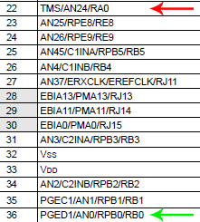
There are two arrows there, red and green. The red arrow is pointing to the bad RA0 that didn't work and green is pointing to the good RB0 that worked fine. If you look next to RA0 you'll see 3 little letters that can mean hours of frustration. TMS. There are more, TCK, TDI and TDO. So what gives?
As we've established by now, Microchip's idea of a default configuration is somewhat different from what a hobbyist wants. This means that every peripheral may be set to the wrong clock speed, everything is set to analog and interfaces like JTAG are enabled by default. What is JTAG? For most of us, it's something that takes away our ability to use the ports that we want :) To prevent many many hours of "reading the datasheet", please ensure you have these fuses set:
#pragma config FWDTEN = OFF             // Watchdog Timer Enable (WDT Disabled) - Enable for random resets
#pragma config FDMTEN = OFF             // Deadman Timer Enable (Deadman Timer is disabled) - See above
#pragma config JTAGEN = OFF             // JTAG Enable (JTAG Disabled) - Enable to lose four port outputs
#pragma config DEBUG = OFF              // Background Debugger Enable (Debugger is disabled) - Set if off and MPLAB will override it when you debug
#pragma config CP = OFF                 // Code Protect (Protection Disabled) - This will encrypt your PIC32 if enabled
#pragma config PMDL1WAY = OFF           // Peripheral Module Disable Configuration (Allow multiple reconfigurations) - Enable to only be allowed to make one change to peripheral pin select settings
#pragma config IOL1WAY = OFF            // Peripheral Pin Select Configuration (Allow multiple reconfigurations) - Enable to only be allowed to make one change to peripheral pin select settings
All these features are great and all but sheesh setting up a PIC32MZ before you can even do anything is a lot of work. That's why I use a skeleton and just copy it over each time. Another long winded explanation done, next time some actual code!
Categories: pic32